Paduak
Original PCB top and bottom
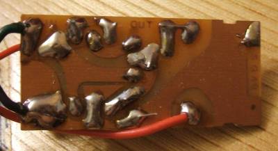
See here for connection details to the pots and switches for the original PCB
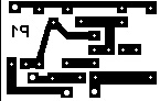
Revised PCB foil pattern - mirrored, see misc
This one is two thirds the size of the originalIt can easily be soldered straight onto the terminals of the on/off switch
Component list
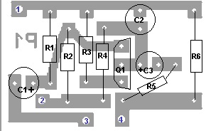
C1, C3 1uF 50v electrolytic C2 10nF MylarResistors (All 1/4W 5%) R1 - 47K R2 - 470K R3 - 270R R4 - 10K R5 - 100K R6 - 68K
Q1 - 2SC1327 (Obsolete, may be hard to find)
External connections 1 - earth 2 +9v 3 - input 4 - output
Component overlay
Testing
Set the switch to the off/bypass position Set your amp gain and volume as low as they will go, so you can only just hear the guitar (This is to prevent possible damage to the amp - and your hearing, the circuit gives a ludicrous amount of boost) Connect the battery (Single PP3) and turn the booster on. It is possible to reduce the level of boost by altering the value of R6 (68k) - lower values give less boost.I would strongly recommend replacing R6 with a 20k/22k resistor and 47k pot wired in series to give variable boost